Home automation with Raspberry Pi - Part 2
Home automation with Raspberry Pi - Part 2
Raspberry Pi GPIO
- One very powerful feature of the Raspberry Pi is the set of General-Purpose Input/Output (GPIO) pins, which act as an interface between the Pi and the outside world. These allow sensors and actuators to be connected and controlled by the Pi.
- The Pi 3B has
40GPI pins as shown in the following picture.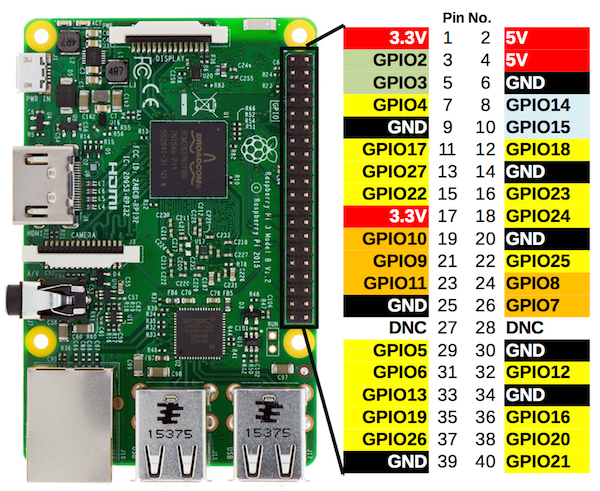
- To identify the GPIO pins, run the
pinoutcommand inside your Pi’s terminal.
The GPIO pins operate on 3.3V logic. As such no sensors that operate at 5V logic should be used.
GPIO programming
- The Pi GPIO can be programmed with a high-level language like Python or low-level language like C or C++. Though C provides much faster performance, Python has more support compared to C: ready-made data structures, algorithms, and modules/libraries, etc. which can easily be used as building blocks. For this reason we stick to Python for GPIO programming. In addition, using Python makes its easier to integrate Web frameworks like Flask when building a control dashboard.
- As an example, we will write a simple program to blink an LED. Create a folder
homeautoand a Python scriptpiauto.pyin that directory.1 2
mkdir homeauto touch piauto.py
- Open this folder in VS Code SSH allowing to edit the Python script.
- Create a virtual environment and install useful Python modules. As seen in previous posts, creating a Python virtual environment isolates our project’s dependencies from other system dependencies.
1
2
3
4
sudo apt install python3-virtualenv          # install virtualenv package systemwide
virtualenv homeautoenv                       # creates virtual environment
source homeautoenv/bin/activate              # activate virtual environment
pip3 install RPi.GPIO                        # install RPi.GPIO module in virtual environment
- In your Python script, import the
RPI.GPIOmodule used to control GPIO pins.1 2
import RPi.GPIO as GPIO from time import sleep
- Declare the pin scheme: this defines how the GPIO pins are numbered. There are two modes:
BCM modewhich refers to the pins by the Broadcom SoC Channel number. In simple language, this means the pin numbering is exactly as shown in the output of the pinout command (GPIOxx). Thee second mode:BOARD modemeans the pin numbering follows the numbering on the plug, i.e., the numbers printed on the board, e.g,. P1 etc. We use the BCM mode.
1
GPIO.setmode(GPIO.BCM)
- Pin modes: The pin mode defines the behaviour of a GPIO pin as an input or output pin. If you wish to control an LED for example, set the pin mode to
OUTPUT. On the other hand, if the pin is to be used as an input pin (e.g., for a temperature sensor) set it as anINPUT pin. We will use pin GPIO14 (see pinout diagram) as an output pin to control our LED. NB: there is nothing special about GPIO pin 14, you can pick any other GPIO pin. We chose pin 14 because it is next to a ground pin (GND) which we need to complete the circuit.
1
2
ledPin = 14
GPIO.setup(ledPin,GPIO.OUT)
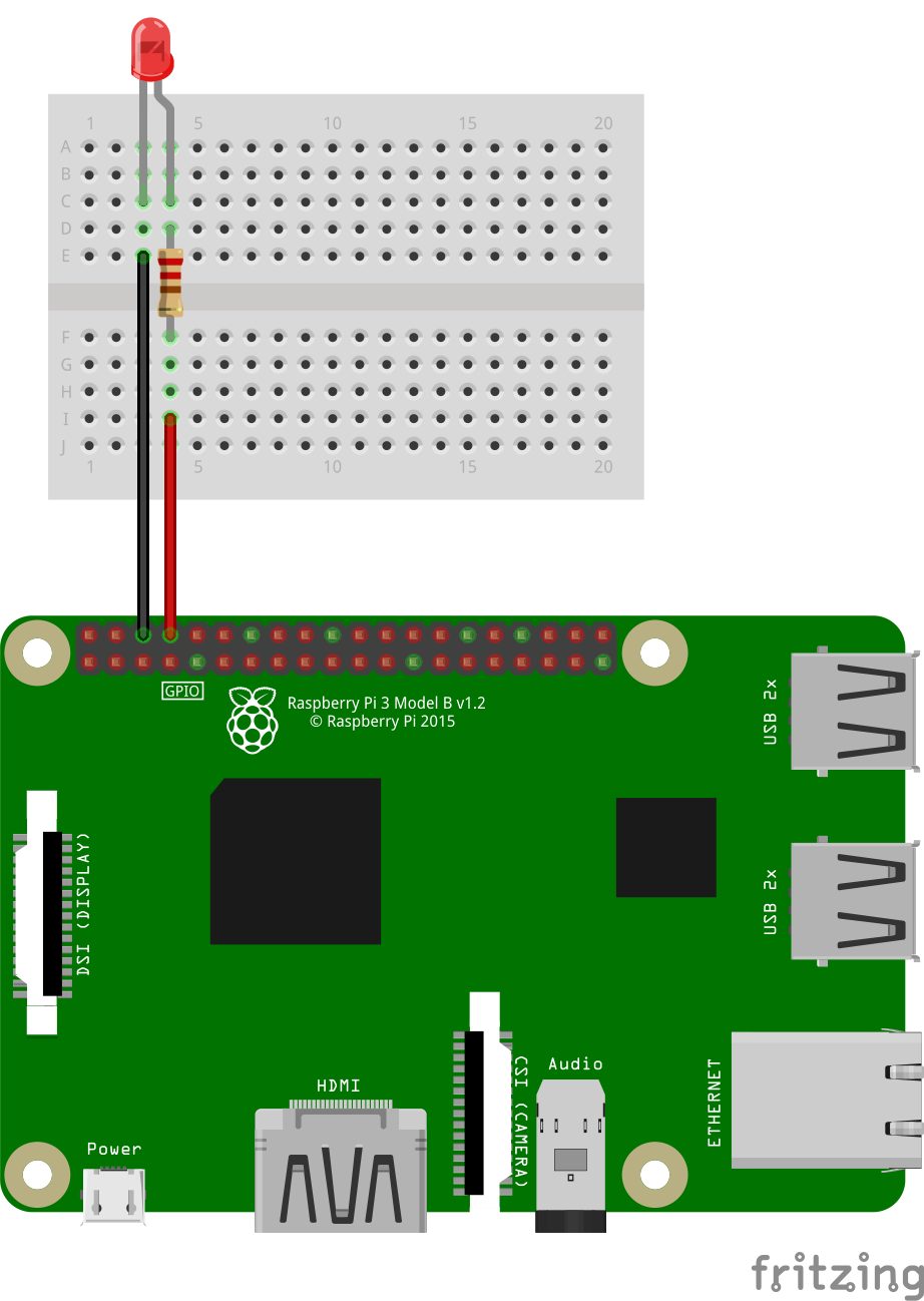
- Connect the LED to this pin using a bread-board as shown in the following sketch. The anode (longer leg: +) of the LED should be connected to a resistor (e.g., 220 Ohm) to reduce the current flowing into the LED. The cathode (shorter leg: -) should be connected to a ground pin (GND) on the Pi board.
- GPIO states: You can set the state of a GPIO output pin high (3.3V) or low (0V). Use
GPIO.output(pin,GPIO.HIGH)orGPIO.output(pin,GPIO.LOW)to set it high or low respectively. To read the status of a GPIO pin, usedigitalRead(pin). You can use software pull-up or pull-down functions to ensure a well-defined state on a pin. To add delays usetime.sleep(delay-in-seconds), e.g.,time.sleep(0.5). You can use PCM to dim LEDs. For analog input, you will need an analog to digital converter (ADC). Some examples of ADC chips: MCP3008, ADS1x15 - To let the LED blink, we create a loop in which we set the LED pin to HIGH and LOW consecutively.
1
2
3
4
5
6
7
while True:                          # Endless Loop
    GPIO.output(ledPin, GPIO.HIGH)   # Turn on
    print("LED on")                  # Prints state to console
    sleep(1)                         # Pause for 1 second
    GPIO.output(ledPin, GPIO.LOW)    # Turn off
    print("LED off")                 # Prints state to console
    sleep(1)                         # Pause for 1 second
- Execute the script with
python3 piauto.py
This post is licensed under CC BY 4.0 by the author.